
Page 368 - Mechanical Behavior of Materials
P. 368
Section 8.5 Additional Topics on Application of K 369
2b
P P P
d
a
S
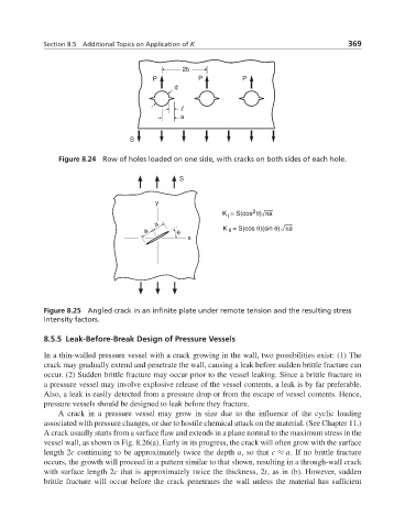
Figure 8.24 Row of holes loaded on one side, with cracks on both sides of each hole.
S
y
2
K = S(cos θ) πa
I
a
a θ K = S(cos θ)(sin θ) πa
II
x
Figure 8.25 Angled crack in an infinite plate under remote tension and the resulting stress
intensity factors.
8.5.5 Leak-Before-Break Design of Pressure Vessels
In a thin-walled pressure vessel with a crack growing in the wall, two possibilities exist: (1) The
crack may gradually extend and penetrate the wall, causing a leak before sudden brittle fracture can
occur. (2) Sudden brittle fracture may occur prior to the vessel leaking. Since a brittle fracture in
a pressure vessel may involve explosive release of the vessel contents, a leak is by far preferable.
Also, a leak is easily detected from a pressure drop or from the escape of vessel contents. Hence,
pressure vessels should be designed to leak before they fracture.
A crack in a pressure vessel may grow in size due to the influence of the cyclic loading
associated with pressure changes, or due to hostile chemical attack on the material. (See Chapter 11.)
A crack usually starts from a surface flaw and extends in a plane normal to the maximum stress in the
vessel wall, as shown in Fig. 8.26(a). Early in its progress, the crack will often grow with the surface
length 2c continuing to be approximately twice the depth a, so that c ≈ a. If no brittle fracture
occurs, the growth will proceed in a pattern similar to that shown, resulting in a through-wall crack
with surface length 2c that is approximately twice the thickness, 2t, as in (b). However, sudden
brittle fracture will occur before the crack penetrates the wall unless the material has sufficient