
Page 361 - Mechanical Behavior of Materials
P. 361
362 Chapter 8 Fracture of Cracked Members
a/t = 0.5
S t 1.5 2
a f = 1.08[1 + 0.1875(1 – sin θ) ]
S b
1.0
a/t = 0
t f 2
h a a f = 1.04[1 + 0.1(1 – sin θ) ]
a
0.5
θ
b
) a ( ) b ( 0 0 π /4 π /2
θ, radians
Functional forms for a/b < 0.5, h/b > 1:
!
2 √ πa a
K = f a f w (S t + f b S b ) πa, f w = sec
π 2b t
where f a = f a (a/t,θ), f b = f b (a/t)
◦
Expressions for θ = 0 and 180 (surface) for any α = a/t:
2
4
2
f a = (1.04 + 0.2017α − 0.1061α )(1.1 + 0.35α ), f b = 1 − 0.45α
◦
Expressions for θ = 90 (deepest point) for any α = a/t:
2
4
f a = 1.04 + 0.2017α − 0.1061α , f b = 1 − 1.34α − 0.03α 2
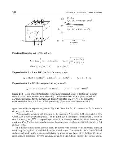
Figure 8.18 Stress intensity factors for rectangular cross sections as in (a) for half-circular
surface cracks under tension and/or bending. The general form for K is given, as well as
particular equations for the surface and deepest point for any a/t. Also, (b) shows the
variation with θ for a/t = 0and 0.5asgiven by f a . (Equations from [Newman 86].)
approximated by the expression given in Fig. 8.19. Note that Eq. 8.21 reduces to Eq. 8.20 for a
circular crack, a/c = 1.
◦
With respect to variation with the angle φ, the maximum K from Eq. 8.21 occurs at φ = 90 ,
where f φ = 1, corresponding to points D on the minor axis of the ellipse. The minimum K occurs at
√
φ = 0, where f φ = a/c, corresponding to points E on the major axis of the ellipse. Denoting the
maximum K as K D , this value may be employed for finite-size members, within 10%, for a/t < 0.4
and c/b < 0.2.
In a manner similar to the circular crack, the closed-form solution for an embedded elliptical
crack may be applied in modified form to related cases. For example, for a half-elliptical
surface crack under uniform stress, multiplying by a free surface factor of 1.12 allows K D to be
approximated. Limitations for 10% accuracy are given in Fig. 8.19, as case (b). For surface cracks