
Page 388 - Mechanical Behavior of Materials
P. 388
388 Chapter 8 Fracture of Cracked Members
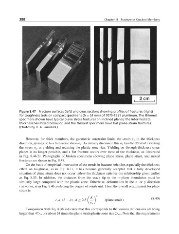
Figure 8.47 Fracture surfaces (left) and cross sections showing profiles of fractures (right)
for toughness tests on compact specimens (b = 51 mm) of 7075-T651 aluminum. The thinnest
specimens shown have typical plane stress fractures on inclined planes; the intermediate
thickness has mixed behavior; and the thickest specimens have flat plane-strain fractures.
(Photos by R. A. Simonds.)
However, for thick members, the geometric constraint limits the strain ε z in the thickness
direction, giving rise to a transverse stress σ z . As already discussed, this σ z has the effect of elevating
the stress σ y at yielding and reducing the plastic zone size. Yielding on through-thickness shear
planes is no longer possible, and a flat fracture occurs over most of the thickness, as illustrated
in Fig. 8.44(b). Photographs of broken specimens showing plane stress, plane strain, and mixed
fractures are shown in Fig. 8.47.
On the basis of empirical observation of the trends in fracture behavior, especially the thickness
effect on toughness, as in Fig. 8.31, it has become generally accepted that a fully developed
situation of plane strain does not occur unless the thickness satisfies the relationship given earlier
as Eq. 8.33. In addition, the distances from the crack tip to the in-plane boundaries must be
similarly large compared with the plastic zone. Otherwise, deformation in the x-or y-direction
can occur, as in Fig. 8.46, reducing the degree of constraint. Thus, the overall requirement for plane
strain is
2
K (8.40)
t, a, (b − a) , h ≥ 2.5 (plane strain)
σ o
Comparison with Eq. 8.38 indicates that this corresponds to the various dimensions all being
larger than 47r oε , or about 24 times the plane strain plastic zone size 2r oε . Note that the requirements