
Page 393 - Mechanical Behavior of Materials
P. 393
394 Chapter 8 Fracture of Cracked Members
P
dU
P
t a
L a + da
1 dU
a da J = –
t da
0 v = ΔL
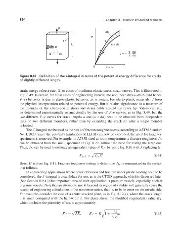
Figure 8.49 Definition of the J-integral in terms of the potential energy difference for cracks
of slightly different length.
strain energy release rate, G, to cases of nonlinear-elastic stress–strain curves. This is illustrated in
Fig. 8.49. However, for most cases of engineering interest, the nonlinear stress–strain (and hence,
P-v) behavior is due to elasto-plastic behavior, as in metals. For elasto-plastic materials, J loses
the physical interpretation related to potential energy. But it retains significance as a measure of
the intensity of the elasto-plastic stress and strain fields around the crack tip. Values can still
be determined experimentally or analytically by the use of P-v curves, as in Fig. 8.49, but the
two different P-v curves for crack lengths a and (a + da) need to be obtained from independent
tests on two different members, rather than by extending the crack da after a single member
is loaded.
The J-integral can be used as the basis of fracture toughness tests, according to ASTM Standard
No. E1820. Since the plasticity limitations of LEFM can now be exceeded, the need for large test
specimens is removed. For example, in A533B steel at room temperature, a fracture toughness J Ic
can be obtained from the small specimen in Fig. 8.29, without the need for testing the large one.
Thus, J Ic can be used to estimate an equivalent value of K Ic by using Eq. 8.10 with J replacing G:
K IcJ = J Ic E (8.44)
Here, E is from Eq. 8.11. Fracture toughness testing to determine J Ic is summarized in the section
that follows.
In engineering applications where crack extension and fracture under plastic loading need to be
considered, the J-integral is a candidate for use, as is the CTOD approach, which is discussed later.
(See Section 8.9.4.) One important area of such application is pressure vessels, especially nuclear
pressure vessels. Note that an attempt to use K beyond its region of validity will generally cause the
results of engineering calculations to be nonconservative, that is, to be in error on the unsafe side.
For example, consider the case of a center-cracked plate, as in Fig. 8.12(a), where the crack length
a is small compared with the half-width b. For plane stress, the modified (equivalent) value K J ,
which includes the plasticity effect, is approximately
√ ! ε p
K J = JE, K J ≈ K 1 + √ (8.45)
ε e n