
Page 398 - Mechanical Behavior of Materials
P. 398
Section 8.10 Summary 399
crack and member geometry; the loading configuration, such as tension or bending; and the ratio of
the crack length to the width of the member, such as the ratio a/b. Some notable values of F for
relatively short cracks under tension stress are as follows:
F = 1.00 (center-cracked plate)
F = 1.12 (through-thickness or circumferential surface crack)
(8.51)
F = 0.73 (half-circular surface crack)
F = 0.72 (quarter-circular corner crack)
It is sometimes convenient to express K in terms of an applied force P by using the differently
defined dimensionless quantity F P according to Eq. 8.13.
The value of K for which a given material begins to crack significantly is called K Q , and the
value for failure is called K c . Slow-stable crack growth may follow K Q until K c is reached, and both
of these may decrease with increased member thickness. If the plastic zone surrounding the crack
tip is quite small compared with the thickness and is very well isolated relative to the boundaries
of the member, then a state of plane strain is established. Under plane strain, only limited slow-
stable crack growth occurs, so that K Q and K c have similar values to each other, and K Q becomes
the standard plane-strain fracture toughness, K Ic . A value of K Ic represents a worst-case fracture
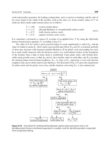
toughness that can be safely used for any thickness. The flowchart of Fig. 8.53 gives the requirement
for plane strain and the plastic zone sizes, and the situation concerning K Ic is also summarized.
START
K 2
Are t, a, (b – a), h 2.5 ( ) ?
σο
Yes No
Then plane strain, and Then plane stress, and
(
(
(1) 2r = 1 K 2 2r = 1 K 2
)
)
oε 3π σo oσ π σ o
(2) LEFM is applicable
Are a, (b – a), h 8r ?
oσ
(planar dimensions)
Yes No
LEFM is applicable
Is the load below 80% of
the fully plastic value?
Yes No
Adjust K values Use J-integral
using (a + r ) or CTOD
oσ
K = K Ic K , K K Ic
Q
Q
c
Ic
(minimum toughness) (slow-stable Δa) K Ic J E
Figure 8.53 Flowchart for distinguishing between plane stress and plane strain, for
deciding what fracture mechanics approach is needed, and for identifying what is expected
from toughness testing.