
Page 395 - Mechanical Behavior of Materials
P. 395
396 Chapter 8 Fracture of Cracked Members
Δa = Δa
5
6 7 8
4
3
2
1 m
B 5
, Force A a = a + Δa 5
5
i
P
m
i A pl
Unloading
m 5 for a = a 5
0 v, Displacement
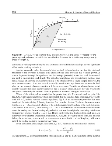
Figure 8.51 Area A pl for calculating the J-integral. Curve A is the actual P-v record for the
growing crack, whereas curve B is the hypothetical P-v curve for a stationary (nongrowing)
crack of length a 5 .
calculated at various points during the test. (Note that the small elastic unloadings have no significant
effect on the cracking behavior.)
Another approach, called the potential drop method, is based on the fact that the electrical
resistance of the specimen increases as its cross-sectional area decreases due to crack growth. A
current is passed through the specimen, and the voltage (potential) across the crack is measured
and used to calculate the crack length. The unloading compliance and potential drop methods have
the advantage of allowing crack extension data to be obtained from a single sample. However, the
most accurate method is to test several nominally identical test specimens and remove the load
after varying amounts of crack extension in different specimens. Then the samples are heated to tint
(slightly oxidize) the fresh fracture surface so that it is easily observed, next they are broken into
two pieces, and finally the amounts of crack growth are measured through a microscope.
Values of the J-integral are needed for the points along the P-v record, such as point 5 in
Fig. 8.50, where crack lengths have been determined. For the standard bend specimen, Fig. 8.13(b)
with h/b = 2, and the standard compact specimen, Fig. 8.16, an approximate procedure has been
developed for determining J directly from the P-v record of the test. To do so, the current crack
length, a = a i + a, is needed, where a i is the initial precrack length and a is the crack extension.
Also needed is the area A pl shown in Fig. 8.51. This is the area under the force versus displacement
curve for loading and then unloading a hypothetical test member originally containing a stationary
(nongrowing) crack of length a = a i + a. Hence, the hypothetical loading slope, such as m 5 ,is
somewhat lower than the actual initial load slope m i . Also, this P-v curve differs from, and deviates
below, the actual one, as the actual curve corresponds to an initial crack of length a i , with crack
growth by gradual tearing to the current a value.
Given the current crack length a and area A pl ,the J value can be determined as follows:
2
2
K (1 − ν )
J = J el + J pl , J el = (8.46)
E
The elastic term J el is obtained from the stress intensity K and the elastic constants of the material