
Page 383 - Mechanical Behavior of Materials
P. 383
384 Chapter 8 Fracture of Cracked Members
8.7.1 Plastic Zone Size for Plane Stress
An equation for estimating plastic zone sizes for plane stress situations can be developed from the
elastic stress field equations, Eq. 8.7, with σ z = 0. In the plane of the crack, where θ = 0, these
simplify to
K
σ x = σ y = √ , σ z = τ xy = τ yz = τ zx = 0 (a, b) (8.35)
2πr
Since all shear stress components along θ = 0 are zero, σ x , σ y , and σ z are principal normal stresses.
Applying either the maximum shear stress or the octahedral shear stress yield criterion of the
previous chapter, we estimate that yielding occurs at σ x = σ y = σ o , where σ o is the yield strength.
Substituting this and solving for r gives
1 K 2
r oσ = (8.36)
2π σ o
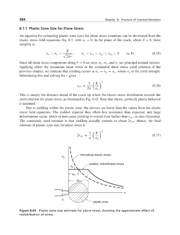
This is simply the distance ahead of the crack tip where the elastic stress distribution exceeds the
yield criterion for plane stress, as illustrated in Fig. 8.43. Note that elastic, perfectly plastic behavior
is assumed.
Due to yielding within the plastic zone, the stresses are lower than the values from the elastic
stress field equations. The yielded material thus offers less resistance than expected, and large
deformations occur, which in turn cause yielding to extend even farther than r oσ , as also illustrated.
The commonly used estimate is that yielding actually extends to about 2r oσ . Hence, the final
estimate of plastic zone size for plane stress is
2
1 K
2r oσ = (8.37)
π σ o
σ y theoretical elastic stress
yielded, redistributed stress
σ o
r oσ
2r oσ
x
δ
plastic zone
Figure 8.43 Plastic zone size estimate for plane stress, showing the approximate effect of
redistribution of stress.