
Page 405 - Moving the Earth_ The Workbook of Excavation
P. 405
BLASTING AND TUNNELING
BLASTING AND TUNNELING 9.5
The whole area is usually machine-stripped, and the actual spots to be drilled are cleaned by
hand. At other times the soil is cleaned off only in slots, and drilling is done in lines along them.
Face Height. A rock mass may be taken out in a single layer, or in a series of benches. Highway
contractors usually prefer benches, as do most open-pit miners, but quarry operators may take single
slices 100 or even 200 feet high. This is partly because quarry rock is often sound enough to stand
at great heights without much danger of collapse.
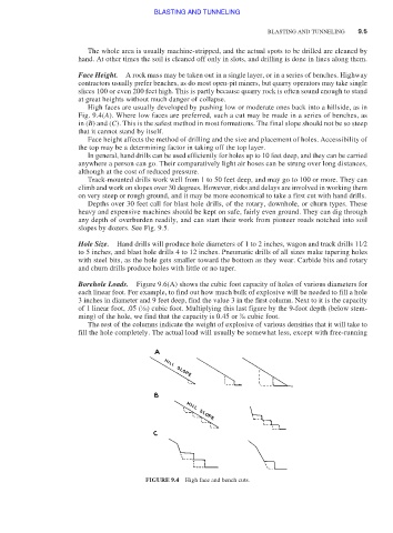
High faces are usually developed by pushing low or moderate ones back into a hillside, as in
Fig. 9.4(A). Where low faces are preferred, such a cut may be made in a series of benches, as
in (B) and (C). This is the safest method in most formations. The final slope should not be so steep
that it cannot stand by itself.
Face height affects the method of drilling and the size and placement of holes. Accessibility of
the top may be a determining factor in taking off the top layer.
In general, hand drills can be used efficiently for holes up to 10 feet deep, and they can be carried
anywhere a person can go. Their comparatively light air hoses can be strung over long distances,
although at the cost of reduced pressure.
Track-mounted drills work well from 1 to 50 feet deep, and may go to 100 or more. They can
climb and work on slopes over 30 degrees. However, risks and delays are involved in working them
on very steep or rough ground, and it may be more economical to take a first cut with hand drills.
Depths over 30 feet call for blast hole drills, of the rotary, downhole, or churn types. These
heavy and expensive machines should be kept on safe, fairly even ground. They can dig through
any depth of overburden readily, and can start their work from pioneer roads notched into soil
slopes by dozers. See Fig. 9.5.
Hole Size. Hand drills will produce hole diameters of 1 to 2 inches, wagon and track drills 11⁄2
to 5 inches, and blast hole drills 4 to 12 inches. Pneumatic drills of all sizes make tapering holes
with steel bits, as the hole gets smaller toward the bottom as they wear. Carbide bits and rotary
and churn drills produce holes with little or no taper.
Borehole Loads. Figure 9.6(A) shows the cubic foot capacity of holes of various diameters for
each linear foot. For example, to find out how much bulk of explosive will be needed to fill a hole
3 inches in diameter and 9 feet deep, find the value 3 in the first column. Next to it is the capacity
1
of 1 linear foot, .05 ( ⁄20) cubic foot. Multiplying this last figure by the 9-foot depth (below stem-
ming) of the hole, we find that the capacity is 0.45 or ⁄20 cubic foot.
9
The rest of the columns indicate the weight of explosive of various densities that it will take to
fill the hole completely. The actual load will usually be somewhat less, except with free-running
FIGURE 9.4 High face and bench cuts.