
Page 309 - Materials Chemistry, Second Edition
P. 309
292 Practical Design Calculations for Groundwater and Soil Remediation
Solution:
After air dilution, heat content of the diluted waste gas is 10 Btu/scf.
Use Equation (7.24) to estimate the temperature of the catalyst bed:
=
+
T = T + 50H = 550 (50)(10) 1,050 °F
out in w
Discussion:
The calculated temperature, 1,050°F, falls in the typical temperature
range for catalyst beds (1,000°F–1,200°F).
7.4.3 Volume of the Catalyst Bed
The total influent to a catalyst bed is the sum of the waste air, dilution air
(and/or the auxiliary air), and the supplementary fuel, and it can be deter-
mined from Equation (7.21):
Q inf = Q w + Q d +
Q sf
In most cases, one can assume that the flow rate of the combined gas
stream, Q , entering the catalyst is approximately equal to the flue gas leav-
inf
ing the catalyst at standard conditions, Q . The flue gas flow rate of actual
fg
conditions can be determined from Equation (7.22):
Q fg,a = Q fg T c + 460 = Q fg T c + 460
77 + 460 537
Because of the short residence time in the catalyst bed, space velocity is
commonly used to relate the volumetric air flow rate and the volume of the
catalyst bed. The space velocity is defined as the volumetric flow rate of the
VOC-laden air entering the catalyst bed divided by the volume of the catalyst
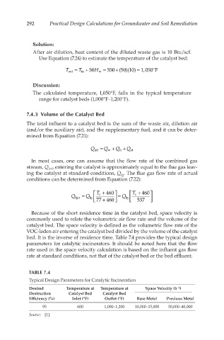
bed. It is the inverse of residence time. Table 7.4 provides the typical design
parameters for catalytic incinerators. It should be noted here that the flow
rate used in the space velocity calculation is based on the influent gas flow
rate at standard conditions, not that of the catalyst bed or the bed effluent.
TABLE 7.4
Typical Design Parameters for Catalytic Incineration
−1
Desired Temperature at Temperature at Space Velocity (h )
Destruction Catalyst Bed Catalyst Bed
Efficiency (%) Inlet (°F) Outlet (°F) Base Metal Precious Metal
95 600 1,000–1,200 10,000–15,000 30,000–40,000
Source: [1].