
Page 306 - Materials Chemistry, Second Edition
P. 306
VOC-Laden Air Treatment 289
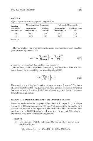
TABLE 7.3
Typical Thermal Incinerator System Design Values
Nonhalogenated Compounds Halogenated Compounds
Required
Destruction Combustion Residence Combustion Residence Time
Efficiency (%) Temperature (°F) Time (sec) Temperature (°F) (sec)
98 1,600 0.75 2,000 1.0
99 1,800 0.75 2,000 1.0
Source: [1].
The flue gas flow rate of actual conditions can be determined from Equation
(7.11) or from Equation (7.22):
Q fg,a = Q fg T c + 460 = Q fg T c + 460 (7.22)
77 + 460 537
where Q fg,a is the actual flue gas flow rate in acfm.
The volume of the combustion chamber, V , is determined from the resi-
c
dence time, τ (in sec), and Q fg,a by using Equation (7.23):
Q fg,a
τ ×
V c = 1.05 (7.23)
60
The equation is nothing but “residence time = volume ÷ flow rate.” The factor
of 1.05 is a safety factor, which is an industrial practice to account for minor
fluctuations in the flow rate. Table 7.3 tabulates the typical thermal incinera-
tor system design values.
Example 7.12: Determine the Size of the Thermal Incinerator
Referring to the remediation project described in Example 7.11, an off-gas
stream (Q = 200 scfm) containing 800 ppmV of xylenes is to be treated by a
thermal oxidizer with a recuperative heat exchanger. The combustion tem-
perature is set at 1,800°F to achieve a destruction efficiency of 99% or higher.
Determine the size of the thermal incinerator.
Solution:
(a) Use Equation (7.21) to determine the flue gas flow rate at stan-
dard conditions:
=
+ +
Q ≈ Q = Q +Q +Q = 2000 2.21 202.2 scfm
fg inf w d sf