
Page 190 -
P. 190
HIGH-RATE GRANULAR MEDIA FILTRATION 8.9
Two basic modes of gravity filter control are commonly found: constant-rate and
declining-rate. With the constant-rate mode, there are three ways to operate a filter: (1) a
rate-of-flow controller in the filtered water piping; (2) influent flow splitting with the wa-
ter level over the filter maintained at a constant level; and (3) influent flow splitting with
the water level varying during the filter run.
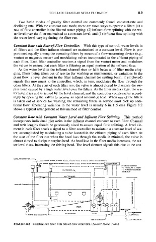
Constant Rate with Rate-of-Flow Controller. With this type of control, water levels in
all filters and the filter influent channel are maintained at a constant level. Flow is pro-
portioned equally among the operating filters by means of a flow-measuring device (e.g.,
venturi or magnetic meter) and modulating valves incorporated in the effluent piping of
each filter. Each filter controller receives a signal from the venturi meter and modulates
the valves to ensure that each filter is filtering an equal portion of the influent flow.
As the water level in the influent channel rises or falls because of filter media clog-
ging, filters being taken out of service for washing or maintenance, or variations in the
plant flow, a level element in the filter influent channel (or settling basin, if employed)
signals this movement to the controller, which, in turn, modulates the flow through the
other filters. At the start of each filter run, the valve is almost closed to dissipate the sur-
plus head caused by a high water level over the filters. As the filter media clogs, the wa-
ter level rises and is sensed by the level element, and the controller compensates accord-
ingly by opening the valves to recover an equal amount of head. When one of the filters
is taken out of service for washing, the remaining filters in service must pick up addi-
tional flow. Operating variation in the water level is usually 6 in. (15 cm). Figure 8.2
shows a typical arrangement of this method of filter control.
Constant Rate with Constant Water Level and Influent Flow Splitting. This method
incorporates individual inlet weirs in the influent channel entrance to each filter. Channel
and weir lengths should be generously sized to ensure equal flow splitting. A level ele-
ment in each filter sends a signal to a filter controller to maintain a constant level of wa-
ter, accomplished by modulating a valve located in the effluent piping of each filter. At
the start of the filter run when the head loss through the media is minimal, the valve is
almost closed to dissipate surplus head. As head loss in the filter media increases, the wa-
ter level rises, increasing the driving head. The level element signals this rise to the con-
--. PE: PRESSURE ELEMENT
FILTER BOX ""~ ~ TE:M: MOToRTURBIDITY ELEMENT
WRT .... I I I J
BACKWASH HEADER ~-
I F,, '.- o
VENTURI METER" t~, CONTROL WEIR
FIGURE 8.2 Constant-rate filter with rate-of-flow controller. (Source: Monk, 1987.)