
Page 191 -
P. 191
8.10 CHAPTER EIGHT
LEVELTRANSMITFER~'~
FE: FLOW ELEMENT
PE: PRESSURE ELEMENT
-- ~ ~ TE:TURBIDITY ELEMENT
/
* ";~__1 ~.,. ~ ~ ~ , * CONTROLLER M:MOTOR
FILTER BOX --~
t
+
WATER LEVEL
INLET WEIR i ~ . TM
HEADER
CHANNEL I
....... ':- iJ l !
"--L~ACKWASH PIPE CO 2TR WE,RS'i DLEmELL
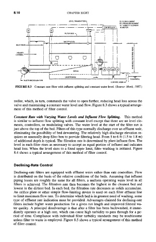
FIGURE 8.3 Constant-rate filter with influent splitting and constant water level. (Source." Monk, 1987.)
troller, which, in turn, commands the valve to open further, reducing head loss across the
valve and maintaining a constant water level and flow. Figure 8.3 shows a typical arrange-
ment of this method of filter control.
Constant Rate with Varying Water Levels and Influent Flow Splitting. This method
is similar to influent flow splitting with constant level except that there are no level ele-
ments, controllers, or modulating valves. The water level at the start of the filter run is
just above the top of the bed. Filters of this type normally discharge over an effluent weir,
eliminating the possibility of bed dewatering. The relatively high discharge elevation re-
quires an unusually deep filter box to provide filtering head. From 5 to 6 ft (1.5 to 1.8 m)
of additional depth is typical. The filtration rate is determined by plant influent flow. The
level in each filter rises as necessary to accept an equal portion of influent and indicates
head loss. When the level rises to a fixed upper limit, filter washing is initiated. Figure
8.4 shows a typical arrangement of this method of filter control.
Declining-Rate Control
Declining-rate filters are equipped with effluent weirs rather than rate controllers. Flow
is distributed on the basis of the relative conditions of the beds. Assuming that influent
piping losses are roughly the same for all filters, a uniform operating water level in all
filters is achieved. The filtration rate then becomes the highest in the cleanest bed and
lowest in the dirtiest bed. In each bed, the filtration rate decreases as solids accumulate.
An orifice plate or other simple flow-limiting device is used on each filter effluent line
to limit maximum flow rate. To determine which bed is in greatest need of washing, some
type of effluent rate indication must be provided. Advantages claimed for declining-rate
filters include higher water production for a given run length and improved filtered wa-
ter quality. A principal disadvantage is that after a filter has been backwashed, it imme-
diately operates at a high rate, which can cause high turbidity to pass through for a pe-
riod of time. Compliance with individual filter turbidity standards may be troublesome
unless filter to waste is employed. Figure 8.5 shows a typical arrangement of this method
of filter control.