
Page 196 -
P. 196
HIGH-RATE GRANULAR MEDIA FILTRATION 8.15
Surface wash systems are typically suspended about 2 in. (5 cm) above the surface of
the unexpanded filter bed and employed prior to introducing washwater during low-rate
backwash. Use of surface wash during high-rate backwash may cause media loss over the
waste troughs. Systems have also been placed in the unexpanded bed of dual- and mixed-
media filters where there is an accumulation of filtered materials deep within the filter
bed. Dual-arm rotary systems that have one arm above and one arm below the unexpanded
surface are also available. Nozzle plugging with media has been a problem with the sub-
merged units.
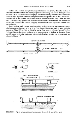
Rotary surface wash systems may have either straight or curved pipe arms and gener-
ally have nozzle diameters of 1~ to 1A in. (3 to 6 mm). Single-arm rotating units typically
operate at 70 to 100 psi (480 to 690 kPa) and at flow rates of 0.5 to 0.7 gpm/ft 2 (1.3 to
1.8 m/h). Standard units are available up to approximately 14 ft (4 m) in diameter. Some
models induct air into the washwater jets. A typical surface agitator and arrangements are
shown in Figure 8.7.
AGITATORA_j~_.~DIAMETER r'~
A A
f LATERAL I RED BRASS '~'
J~
vpL O - -
I CENTER NOZZLE "~'~ LTJ~
ZZLE
~
END CAP SECTION "A - A"
.~. . / /
'
BURFACE AGITATOR HEADER
~
7
FIGURE 8.7 Typical surface agitator and arrangements. (Source: F. B. Leopold Co., Inc.)