
Page 379 -
P. 379
ION EXCHANGE APPLICATIONS IN WATER TREATMENT 12.37
REGENERANT DISTRIBUTOR
v/A~qmJilL~',AIRm~Jr~h,',AvA
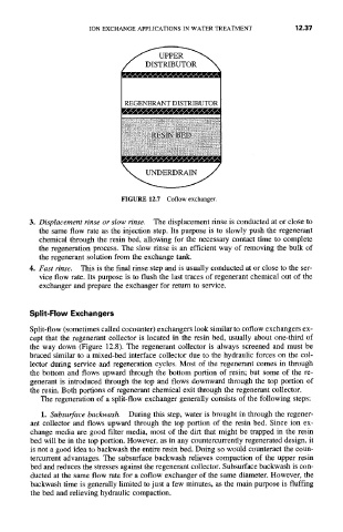
FIGURE 12.7 Coflow exchanger.
3. Displacement rinse or slow rinse. The displacement rinse is conducted at or close to
the same flow rate as the injection step. Its purpose is to slowly push the regenerant
chemical through the resin bed, allowing for the necessary contact time to complete
the regeneration process. The slow rinse is an efficient way of removing the bulk of
the regenerant solution from the exchange tank.
4. Fast rinse. This is the final rinse step and is usually conducted at or close to the ser-
vice flow rate. Its purpose is to flush the last traces of regenerant chemical out of the
exchanger and prepare the exchanger for return to service.
Split-Flow Exchangers
Split-flow (sometimes called cocounter) exchangers look similar to coflow exchangers ex-
cept that the regenerant collector is located in the resin bed, usually about one-third of
the way down (Figure 12.8). The regenerant collector is always screened and must be
braced similar to a mixed-bed interface collector due to the hydraulic forces on the col-
lector during service and regeneration cycles. Most of the regenerant comes in through
the bottom and flows upward through the bottom portion of resin; but some of the re-
generant is introduced through the top and flows downward through the top portion of
the resin. Both portions of regenerant chemical exit through the regenerant collector.
The regeneration of a split-flow exchanger generally consists of the following steps:
1. Subsurface backwash. During this step, water is brought in through the regener-
ant collector and flows upward through the top portion of the resin bed. Since ion ex-
change media are good filter media, most of the dirt that might be trapped in the resin
bed will be in the top portion. However, as in any countercurrently regenerated design, it
is not a good idea to backwash the entire resin bed. Doing so would counteract the coun-
tercurrent advantages. The subsurface backwash relieves compaction of the upper resin
bed and reduces the stresses against the regenerant collector. Subsurface backwash is con-
ducted at the same flow rate for a coflow exchanger of the same diameter. However, the
backwash time is generally limited to just a few minutes, as the main purpose is fluffing
the bed and relieving hydraulic compaction.