
Page 434 -
P. 434
MEMBRANE PROCESSES 13.31
Fouling or scaling occurs when inorganic scales, suspended solids, organics, or biofilms
collect on the membrane surface or the membrane module. Proper pretreatment system
design should minimize membrane fouling. A membrane cleaning system should be in-
cluded in the design to periodically clean and restore membrane performance.
Product (or permeate) pressure must be offset by feedwater pressure to produce the
proper net driving pressure. Feed pump requirements are minimized by designing the fa-
cility for minimum permeate backpressure. For some tow-pressure RO and NF systems,
a permeate backpressure valve is installed for the first stage to help balance flux rates
throughout the system in an attempt to minimize fouling. Some membrane manufactur-
ers specify maximum allowable permeate pressures for their products to prevent module
damage.
Membrane Module Arrays and Staging. The arrangement of membrane modules used
to achieve the desired process flow or optimum hydraulic configuration is called the mem-
brane module array. Arrays are based on the number and location of pressure vessels
(modules or permeators). For example, a 2:1 array would have two parallel pressure ves-
sels feeding one. Depending on the quality of the feedwater or permeate quality require-
ments, RO and NF system arrays are either concentrate-staged or permeate-staged. Some-
times permeate staging is referred to as multiple "passes."
Concentrate-Staged Design. Standard 40-in.-long (102-cm) spiral-wound RO or NF
membrane elements have a maximum individual operating recovery of 8% to 15%. To
achieve higher recoveries, up to eight elements are loaded in series into pressure vessels,
with the concentrate flow from the first element becoming the feed flow to the second el-
ement, and so on.
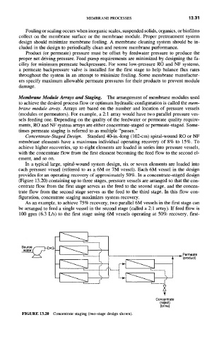
In a typical large, spiral-wound system design, six or seven elements are loaded into
each pressure vessel (referred to as a 6M or 7M vessel). Each 6M vessel in the design
provides for an operating recovery of approximately 50%. In a concentrate-staged design
(Figure 13.20) containing up to three stages, pressure vessels are arranged so that the con-
centrate flow from the first stage serves as the feed to the second stage, and the concen-
trate flow from the second stage serves as the feed to the third stage. In this flow con-
figuration, concentrate staging maximizes system recovery.
As an example, to achieve 75% recovery, two parallel 6M vessels in the first stage can
be arranged to feed a single vessel in the second stage (called a 2:1 array). If feed flow is
100 gpm (6.3 L/s) to the first stage using 6M vessels operating at 50% recovery, first-
Sou rce ,.,.------t_b< ~
water ~ "
Permeate
L ........ I
}~ (product)
'_ ........ ~,---J
I ......... I
Concentrate
(re ect)
(br ne)
FIGURE 13.20 Concentrate staging (two-stage design shown).