
Page 59 -
P. 59
INTAKE FACILITIES 4. ] 1
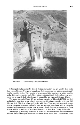
FIGURE 4.7 Diamond Valley Lake inlet/outlet tower.
Submerged intakes generally do not obstruct navigation and are usually less costly
than exposed towers. If properly located and designed, submerged intakes are not signif-
icantly impacted by ice. They consist of a submerged inlet structure, an intake conduit,
and a shore shaft or suction well. Shore intakes are occasionally built on lakes and reser-
voirs, but in general, their effectiveness is reduced by ice, sand, and floating debris.
The intake shown in Figure 4.9 has an initial capacity of 44 mgd (167 ML per day)
and includes provisions to add a fourth screen to provide a future capacity of 65 mgd (246
ML per day). This is a submerged intake with three T-shaped, stainless steel passive
screens connected to a common header pipe. Each screen is equipped with an internally
mounted air backwash connection used to remove debris from the screen surface. These
screens will be located in the Woodward Reservoir in Stanislaus County, California.
An example of a floating intake can be found on Canyon Lake in southern California.
Elsinore Valley Municipal Water District draws source water from Canyon Lake for its