
Page 63 -
P. 63
4.14 CHAPTER FOUR
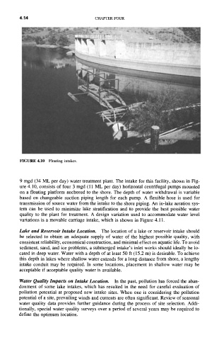
FIGURE 4.10 Floating intakes.
9 mgd (34 ML per day) water treatment plant. The intake for this facility, shown in Fig-
ure 4.10, consists of four 3 mgd (11 ML per day) horizontal centrifugal pumps mounted
on a floating platform anchored to the shore. The depth of water withdrawal is variable
based on changeable suction piping length for each pump. A flexible hose is used for
transmission of source water from the intake to the shore piping. An in-lake aeration sys-
tem can be used to minimize lake stratification and to provide the best possible water
quality to the plant for treatment. A design variation used to accommodate water level
variations is a movable carriage intake, which is shown in Figure 4.11.
Lake and Reservoir Intake Location. The location of a lake or reservoir intake should
be selected to obtain an adequate supply of water of the highest possible quality, with
consistent reliability, economical construction, and minimal effect on aquatic life. To avoid
sediment, sand, and ice problems, a submerged intake's inlet works should ideally be lo-
cated in deep water. Water with a depth of at least 50 ft (15.2 m) is desirable. To achieve
this depth in lakes where shallow water extends for a long distance from shore, a lengthy
intake conduit may be required. In some locations, placement in shallow water may be
acceptable if acceptable quality water is available.
Water Quality Impacts on Intake Location. In the past, pollution has forced the aban-
donment of some lake intakes, which has resulted in the need for careful evaluation of
pollution potential at proposed new intake sites. When one is considering the pollution
potential of a site, prevailing winds and currents are often significant. Review of seasonal
water quality data provides further guidance during the process of site selection. Addi-
tionally, special water quality surveys over a period of several years may be required to
define the optimum location.