
Page 68 -
P. 68
INTAKE FACILITIES 4.19
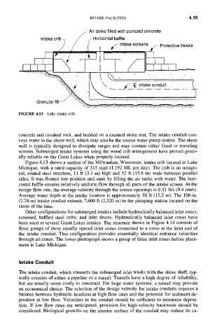
f Air tanks filled with pumped concrete
Intake crib -~ / f Horizontal baffle
/ [ #,./-Intake screens ~- Protective blocks
__
-~'~# ~ \----- ----/¢- ~ intake c3nduit ..... L
Granular fill J "~% '.~-~2..~ ;~'~>.~ ' ~ " ;" . ~ :" ~. ~>
FIGURE 4.13 Lake intake crib.
concrete and crushed rock, and bedded on a crushed stone mat. The intake conduit con-
veys water to the shore well, which may also be the source water pump station. The shore
well is typically designed to dissipate surges and may contain either fixed or traveling
screens. Submerged intake systems using the wood crib arrangement have proved gener-
ally reliable on the Great Lakes when properly located.
Figure 4.13 shows a section of the Milwaukee, Wisconsin, intake crib located in Lake
Michigan, with a rated capacity of 315 mgd (1,192 ML per day). The crib is an octago-
nal, coated steel structure, 11 ft (3.3 m) high and 52 ft (15.8 m) wide between parallel
sides. It was floated into position and sunk by filling the air tanks with water. The hori-
zontal baffle ensures relatively uniform flow through all parts of the intake screen. At the
design flow rate, the average velocity through the screen openings is 0.31 ft/s (9.4 crrds).
Average water depth at the intake location is approximately 50 ft (15.2 m). The 108-in.
(2.74-m) intake conduit extends 7,600 ft (2,320 m) to the pumping station located on the
shore of the lake.
Other configurations for submerged intakes include hydraulically balanced inlet cones;
screened, baffled steel cribs; and inlet drums. Hydraulically balanced inlet cones have
been used at several Great Lakes intakes. The structure shown in Figure 4.14 consists of
three groups of three equally spaced inlet cones connected to a cross at the inlet end of
the intake conduit. This configuration provides essentially identical entrance velocities
through all cones. The lower photograph shows a group of three inlet cones before place-
ment in Lake Michigan.
Intake Conduit
The intake conduit, which connects the submerged inlet works with the shore shaft, typ-
ically consists of either a pipeline or a tunnel. Tunnels have a high degree of reliability,
but are usually more cosily to construct. For large water systems, a tunnel may provide
an economical choice. The selection of the design velocity for intake conduits requires a
balance between hydraulic headloss at high flow rates and the potential for sediment de-
position at low flow. Velocities in the conduit should be sufficient to minimize deposi-
tion. If low flow rates are anticipated, provision for high-velocity backwash should be
considered. Biological growths on the interior surface of the conduit may reduce its ca-