
Page 70 -
P. 70
INTAKE FACILITIES 4.21
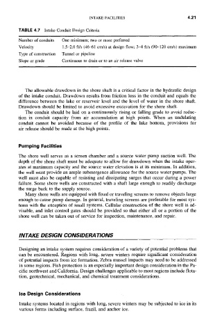
TABLE 4.7 Intake Conduit Design Criteria
Number of conduits One minimum; two or more preferred
Velocity 1.5-2.0 ft/s (46-61 cm/s) at design flow; 3-4 ft/s (90-120 cngs) maximum
Type of construction Tunnel or pipeline
Slope or grade Continuous to drain or to an air release valve
The allowable drawdown in the shore shaft is a critical factor in the hydraulic design
of the intake conduit. Drawdown results from friction loss in the conduit and equals the
difference between the lake or reservoir level and the level of water in the shore shaft.
Drawdown should be limited to avoid excessive excavation for the shore shaft.
The conduit should be laid on a continuously rising or falling grade to avoid reduc-
tion in conduit capacity from air accumulation at high points. When an undulating
conduit cannot be avoided because of the profile of the lake bottom, provisions for
air release should be made at the high points.
Pumping Facilities
The shore well serves as a screen chamber and a source water pump suction well. The
depth of the shore shaft must be adequate to allow for drawdown when the intake oper-
ates at maximum capacity and the source water elevation is at its minimum. In addition,
the well must provide an ample submergence allowance for the source water pumps. The
well must also be capable of resisting and dissipating surges that occur during a power
failure. Some shore wells are constructed with a shaft large enough to readily discharge
the surge back to the supply source.
Many shore wells are equipped with fixed or traveling screens to remove objects large
enough to cause pump damage. In general, traveling screens are preferable for most sys-
tems with the exception of small systems. Cellular construction of the shore well is ad-
visable, and inlet control gates should be provided so that either all or a portion of the
shore well can be taken out of service for inspection, maintenance, and repair.
INTAKE DESIGN CONSIDERATIONS
Designing an intake system requires consideration of a variety of potential problems that
can be encountered. Regions with long, severe winters require significant consideration
of potential impacts from ice formation. Zebra mussel impacts may need to be addressed
in some regions. Fish protection is an especially important design consideration in the Pa-
cific northwest and California. Design challenges applicable to most regions include flota-
tion, geotechnical, mechanical, and chemical treatment considerations.
Ice Design Considerations
Intake systems located in regions with long, severe winters may be subjected to ice in its
various forms including surface, frazil, and anchor ice.