
Page 66 -
P. 66
INTAKE FACILITIES 4.17
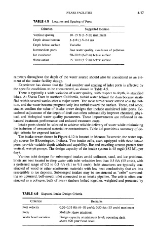
TABLE 4.5 Location and Spacing of Ports
Criterion Suggested location
Vertical spacing 10-15 ft (3-5 m) maximum
Depth above bottom 5-8 ft (1.5-2.4 m)
Depth below surface Variable
Intermediate ports Best water quality, avoidance of pollution
Ice avoidance 20-30 ft (6-9 m) below surface
Wave action 15-30 ft (5-9 m) below surface
rameters throughout the depth of the water source should also be considered as an ele-
ment of the intake facility design.
Experience has shown that the final number and spacing of inlet ports is affected by
the specific conditions to be encountered, as shown in Table 4.5.
There is typically a wide variation of water quality, with respect to depth, in stratified
lakes. At Shasta Dam in northem California, turbid water behind the dam became strati-
fied within several weeks after a major storm. The most turbid water settled near the bot-
tom, and the water became progressively less turbid toward the surface. These, and other,
studies confirm the value of intake tower designs that include multilevel inlet ports. Oc-
casional adjustment of the depth of draft can often substantially improve chemical, phys-
ical, and biological water quality parameters. These improvements are reflected in en-
hanced treatment performance and reduced treatment costs.
Intake ports should be selected to achieve reliable delivery of water while minimizing
the inclusion of unwanted material or contaminants. Table 4.6 provides a summary of de-
sign criteria for exposed intakes.
The intake tower shown in Figure 4.12 is located in Monroe Reservoir, the water sup-
ply source for Bloomington, Indiana. Two intake cells, each equipped with three intake
ports, provide variable depth withdrawal capability. Bar and traveling screens protect four
vertical, wet-pit pumps. The design capacity of the intake system is 48 mgd (182 ML per
day).
Various inlet designs for submerged intakes avoid sediment, sand, and ice problems.
Inlets are best located in deep water with inlet velocities less than 0.5 ft/s (15 cm/s), with
a preferred range of 0.2 to 0.3 ft/s (6.1 to 9.1 cm/s). Inlet structures are typically con-
structed of wood or other nonferrous materials with low heat conductivity that are less
susceptible to ice deposits. Submerged intakes may be constructed as "cribs" surround-
ing an upturned, bell-mouth inlet connected to an intake pipeline. The crib is often con-
structed as a polygon, built of heavy timbers bolted together, weighted and protected by
TABLE 4.6 Exposed Intake Design Criteria
Criterion Remarks
Port velocity 0.20-0.33 ft/s (6-10 cm/s); 0.50 ft/s (15 crn/s) maximum
Ports Multiple; three minimum
Water level variation Design capacity at minimum level; operating deck
above 500-year flood level