
Page 64 -
P. 64
INTAKE FACILITIES 4.15
High water
Low water I ~/.~".,~---~'#~/-/ " /
. . ~ .... '"--J Rubber section
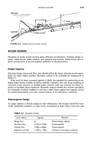
FIGURE 4,11 Intake pump on movable carriage.
INTAKE DESIGN
Designing an intake system involves many different considerations including design ca-
pacity, intake layout, intake conduits, and pumping requirements. Intake design also re-
quires consideration of several potential problems, as discussed below.
Design Capacity
Selecting design criteria and flow rates should reflect the longer planning period appro-
priate for major intake facilities. Hydraulic criteria to be evaluated are summarized in
Table 4.3.
If the need for future increased capacity is likely, the potential for constructing an en-
larged intake facility initially should be carefully evaluated. This may mean installing an
oversized screen structure or parallel intake conduits (with one reserved for future ca-
pacity) to facilitate future expansion. Hydraulic analysis should also include calculation
of a hydraulic overload condition to provide a safety factor against lost capacity caused
by conduit deterioration over time, conduit fouling, or for emergency conditions.
Submergence Design
As intake capacity is directly related to inlet submergence, the designer should be aware
of the substantial variations in water levels encountered in many lakes, reservoirs, and
TABLE 4.3 Hydraulic Criteria
Flow criteria Capacity Remarks
Design flow Q Present design capacity
Minimum flow 0.10Q to 0.20Q System-specific
Ultimate flow 2.00Q or higher System-specific
Evaluate for all design conditions
Hydraulic overload 1.25Q to 1.50Q