
Page 80 -
P. 80
INTAKE FACILITIES 4.31
The choice of chemical treatment to be applied at the intake must be coordinated with
overall optimization of the water treatment process, including the control of disinfection
by-product formation. Historically, chlorine has been used as the standard treatment to
oxidize taste and odor compounds at the intake structure. However, current practice is to
avoid the early use of chlorine in the treatment process where the level of organics in the
source water is highest because of the potential for forming chlorinated disinfection by-
products such as trihalomethanes. Chlorine dioxide, potassium permanganate, and carbon
are alternatives to chlorine that avoid or minimize the formation of chlorinated disinfec-
tion by-products.
RACKS AND SCREENS
Racks and screens remove suspended particulates from water, including leaves, debris,
and other sizable clogging material. Racks and screens are essential to providing protec-
tion for downstream conduits, pumps, and treatment works. Properly designed intake racks
and screens can also minimize the effect on fish.
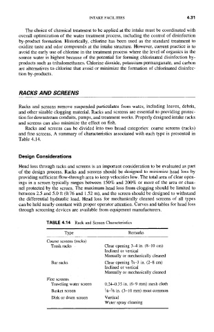
Racks and screens can be divided into two broad categories: coarse screens (racks)
and fine screens. A summary of characteristics associated with each type is presented in
Table 4.14.
Design Considerations
Head loss through racks and screens is an important consideration to be evaluated as part
of the design process. Racks and screens should be designed to minimize head loss by
providing sufficient flow-through area to keep velocities low. The total area of clear open-
ings in a screen typically ranges between 150% and 200% or more of the area or chan-
nel protected by the screen. The maximum head loss from clogging should be limited to
between 2.5 and 5.0 ft (0.76 and 1.52 m), and the screen should be designed to withstand
the differential hydraulic load. Head loss for mechanically cleaned screens of all types
can be held nearly constant with proper operator attention. Curves and tables for head loss
through screening devices are available from equipment manufacturers.
TABLE 4.14 Rack and Screen Characteristics
Type Remarks
Coarse screens (racks)
Trash racks Clear opening 34 in. (8-10 cm)
Inclined or vertical
Manually or mechanically cleaned
Clear opening 3,4-3 in. (2-8 cm)
Barracks
Inclined or vertical
Manually or mechanically cleaned
Fine screens
Traveling water screen 0.24~).35 in. (6-9 mm) mesh cloth
1/~_3/~ in. (3-10 mm) most common
Basket screen
Disk or drum screen Vertical
Water spray cleaning