
Page 167 - 15 Dangerously Mad Projects for the Evil Genius
P. 167
Chapter 11 ■ Flash Bomb 145
If you look closely at the micro-switch, its three Carefully fit the battery back in. Nothing will
pins will normally be labeled Common, NC happen immediately since the flash has not been
(normally closed), and NO (normally open). Solder turned on. Before you do that, hold down the lever
your leads to the NC and Common connections. If on the micro-switch and then with the other hand
your micro-switch is not labeled in this way, then (using something insulating such as plastic) press
test it with the continuity setting on your in the switch on the circuit board for eight seconds.
multimeter to determine the normally closed and You should hear the charging circuit kick into
common connections. action and after a few seconds the indicator light
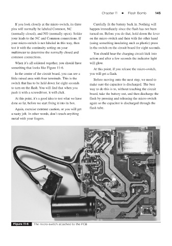
When it’s all soldered together, you should have will glow.
something that looks like Figure 11-6. At this point, if you release the micro-switch,
In the center of the circuit board, you can see a you will get a flash.
little raised area with four terminals. This is the
Before moving onto the next step, we need to
switch that has to be held down for eight seconds
make sure the capacitor is discharged. The best
to turn on the flash. You will find that when you
way to do this is to, without touching the circuit
push it with a screwdriver, it will click.
board, take the battery out, and then discharge the
At this point, it’s a good idea to test what we have flash by pressing and releasing the micro-switch
done so far, before we start fixing it into its box. again so the capacitor is discharged through the
flash tube.
Again, exercise extreme caution, or you will get
a nasty jolt. In other words, don’t touch anything
metal with your fingers.
Figure 11-6 The micro-switch attached to the PCB