
Page 168 - 15 Dangerously Mad Projects for the Evil Genius
P. 168
146 15 Dangerously Mad Projects for the Evil Genius
Step 3. Box the Project
As you can see from Figure 11-1 earlier, the PCB
is simply glued to the bottom of the plastic food
container using a hot glue gun. But before doing
that, we need to drill a small hole opposite the
push switch that turns the flash on. We will then be
able to poke a toothpick in it to turn the device on.
The glue will stick better if the plastic container
is roughened with sandpaper.
Figure 11-7 shows the open box with the PCB
glued inside.
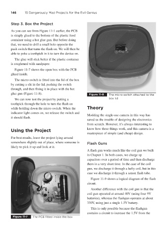
The micro-switch is fitted into the lid of the box
by cutting a slit in the lid, pushing the switch
through, and then fixing it in place with the hot
glue gun (Figure 11-8). Figure 11-8 The micro-switch attached to the
We can now test the project by putting a box lid
toothpick through the hole to turn the flash on
while holding down the micro-switch. When the Theory
indicator light comes on, we release the switch and
Modding the single-use camera in this way has
it should flash.
saved us the trouble of designing the electronics
from scratch. However, it’s always interesting to
Using the Project know how these things work, and this camera is a
masterpiece of simple (and cheap) design.
For best results, leave the project lying around
somewhere slightly out of place, where someone is
Flash Guns
likely to pick it up and look at it.
A flash gun works much like the coil gun we built
in Chapter 1. In both cases, we charge up
capacitors over a period of time and then discharge
them in a very short time. In the case of the coil
gun, we discharge it through a hefty coil, but in this
case we discharge it through a xenon flash tube.
Figure 11-9 shows a logical diagram of the flash
circuit.
Another difference with the coil gun is that the
coil gun operated at around 40V (using four 9V
batteries), whereas the flashgun operates at about
330V, using just a single 1.5V battery.
This is only possible because the flashgun
contains a circuit to increase the 1.5V from the
Figure 11-7 The PCB fitted inside the box