
Page 173 - 15 Dangerously Mad Projects for the Evil Genius
P. 173
Chapter 12 ■ High-Brightness LED Strobe 151
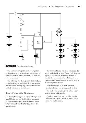
Figure 12-2 The schematic diagram
The LEDs are arranged in a six-by-six pattern The stripboard tracks will need breaking at the
on the main area of the stripboard, with an area of places marked with an X on Figure 12-3. Note that
the board reserved for the transistor 555 timer and Figure 12-3 shows the board from the top. To
other components. translate the positions to where the track is to be
The following step-by-step instructions lead you cut underneath, it can be useful to push a piece of
through making the strobe light. Everything apart wire through from the top.
from the switch, battery clip, and variable resistor Many breaks need to be made, so check
are built onto a piece of stripboard. carefully to be sure you have made all of them.
The back of the stripboard with all the breaks
Step 1. Prepare the Stripboard made is shown in Figure 12-4.
Cut the stripboard to give an area of 29 strips, each Check the stripboard very carefully to make
with 38 holes. You can do this with a strong pair sure all the track breaks are in the correct place
of scissors or by scoring both sides of the board before you start soldering.
with a craft knife and then breaking it over the
edge of a table.