
Page 176 - 15 Dangerously Mad Projects for the Evil Genius
P. 176
Chapter 12 ■ High-Brightness LED Strobe 153
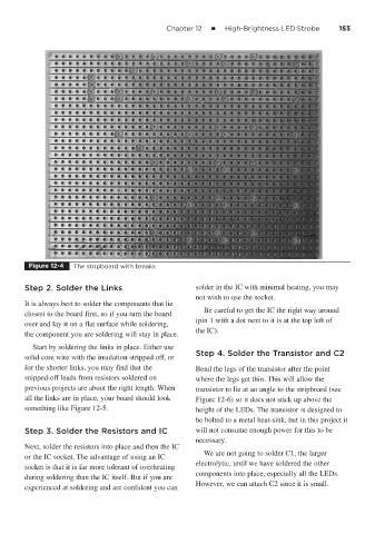
Figure 12-4 The stripboard with breaks
Step 2. Solder the Links solder in the IC with minimal heating, you may
not wish to use the socket.
It is always best to solder the components that lie
Be careful to get the IC the right way around
closest to the board first, so if you turn the board
(pin 1 with a dot next to it is at the top left of
over and lay it on a flat surface while soldering,
the IC).
the component you are soldering will stay in place.
Start by soldering the links in place. Either use
Step 4. Solder the Transistor and C2
solid core wire with the insulation stripped off, or
for the shorter links, you may find that the Bend the legs of the transistor after the point
snipped-off leads from resistors soldered on where the legs get thin. This will allow the
previous projects are about the right length. When transistor to lie at an angle to the stripboard (see
all the links are in place, your board should look Figure 12-6) so it does not stick up above the
something like Figure 12-5. height of the LEDs. The transistor is designed to
be bolted to a metal heat-sink, but in this project it
Step 3. Solder the Resistors and IC will not consume enough power for this to be
necessary.
Next, solder the resistors into place and then the IC
We are not going to solder C1, the larger
or the IC socket. The advantage of using an IC
electrolytic, until we have soldered the other
socket is that it is far more tolerant of overheating
components into place, especially all the LEDs.
during soldering than the IC itself. But if you are
However, we can attach C2 since it is small.
experienced at soldering and are confident you can