
Page 178 - 15 Dangerously Mad Projects for the Evil Genius
P. 178
Chapter 12 ■ High-Brightness LED Strobe 155
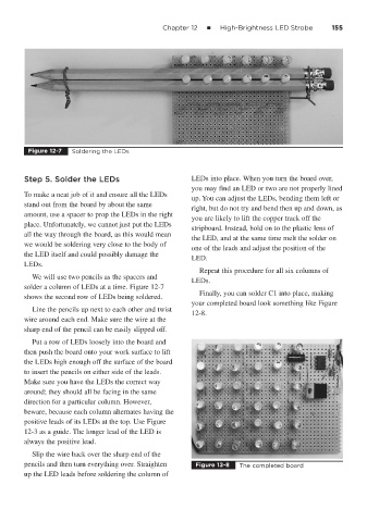
Figure 12-7 Soldering the LEDs
Step 5. Solder the LEDs LEDs into place. When you turn the board over,
you may find an LED or two are not properly lined
To make a neat job of it and ensure all the LEDs
up. You can adjust the LEDs, bending them left or
stand out from the board by about the same
right, but do not try and bend then up and down, as
amount, use a spacer to prop the LEDs in the right
you are likely to lift the copper track off the
place. Unfortunately, we cannot just put the LEDs
stripboard. Instead, hold on to the plastic lens of
all the way through the board, as this would mean
the LED, and at the same time melt the solder on
we would be soldering very close to the body of
one of the leads and adjust the position of the
the LED itself and could possibly damage the
LED.
LEDs.
Repeat this procedure for all six columns of
We will use two pencils as the spacers and
LEDs.
solder a column of LEDs at a time. Figure 12-7
Finally, you can solder C1 into place, making
shows the second row of LEDs being soldered.
your completed board look something like Figure
Line the pencils up next to each other and twist
12-8.
wire around each end. Make sure the wire at the
sharp end of the pencil can be easily slipped off.
Put a row of LEDs loosely into the board and
then push the board onto your work surface to lift
the LEDs high enough off the surface of the board
to insert the pencils on either side of the leads.
Make sure you have the LEDs the correct way
around; they should all be facing in the same
direction for a particular column. However,
beware, because each column alternates having the
positive leads of its LEDs at the top. Use Figure
12-3 as a guide. The longer lead of the LED is
always the positive lead.
Slip the wire back over the sharp end of the
pencils and then turn everything over. Straighten Figure 12-8 The completed board
up the LED leads before soldering the column of