
Page 179 - 15 Dangerously Mad Projects for the Evil Genius
P. 179
156 15 Dangerously Mad Projects for the Evil Genius
Step 6. Drill the Project Box
The project is contained in a plastic food container.
The container has holes drilled for the switch and
the variable resistor on the side. Since the LEDs
will generate some heat, it is probably wise to drill
some ventilation holes in the back of the box to
allow excess heat to escape.
Figure 12-9 shows the box drilled and ready for
the components to be fitted.
Figure 12-9 Drilling the box
Step 7. Wire Up
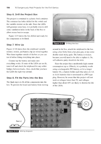
Figure 12-10 shows how the stripboard variable around in the box, attach the stripboard to the box
resistor, switch, and battery clip are wired together. using a few blobs from a hot glue gun, or use some
Wire them together outside of the box so you can double-sided sticky pads. The battery is trickier,
test it before fitting everything into place. because you will need to be able to replace it. So,
Connect up the battery and make sure self-adhesive putty should do the trick.
everything works. If some of the LEDs are not lit, Since the project has a moderately high current
turn it off and check the stripboard for any solder consumption (up to 150mA), it is probably worth
bridges between tracks. Also, check that you have using a rechargeable PP3 battery, or for a longer
the LEDs the right way around. battery life, a battery holder pack that takes six AA
or AAA batteries that is terminated in a PP3-type
Step 8. Fit the Parts into the Box plug. However, be aware that this project will not
work at voltages lower than 9V, and voltages
The final step is to fit all the components into the
higher than about 10V are likely to shorten the life
box. To prevent the board and battery from moving
of the LEDs.
Figure 12-10 Wiring diagram