
Page 166 - 15 Dangerously Mad Projects for the Evil Genius
P. 166
144 15 Dangerously Mad Projects for the Evil Genius
capacitor. If the capacitor was charged, there will If you are using a different type of camera, then
be a big bang and sparks, and your screwdriver it is worth taking note of the battery polarity when
will have scorch marks on it. disassembling the camera
However, if you have followed the instructions Directly beneath the capacitor you should see a
and only disassembled the camera when long metal contact. Directly beneath that is a
discharged, you should get no more than a little second shorter contact. It is these contacts that are
pop as the residual charge in the capacitor is closed by the shutter when it opens to allow light
discharged. to reach the film.
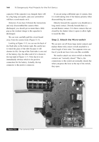
We can now carefully pull the circuit board
away from the camera body (Figure 11-5). Step 2. Attach the Micro-switch
Looking at Figure 11-5, we can see the back of We can now cut off those large metal contacts and
the flash tube on the bottom right. Be careful not replace them with a micro-switch attached to a
to touch the glass of the tube because it will short length of twin wire. Two separate wires are
shorten its life. On top of the flash tube is one end fine if you do not have twin core flex available.
of the battery clip; the other end of it is shown in
We need to attach our micro-switch so that the
the top right of Figure 11-5. Note that it is not
contacts are “normally closed.” That is, the
immediately obvious which is the positive
connections to the switch are normally closed, but
connection for the battery. Actually, the top
when you press the lever at the top of the switch,
connector is the positive connector.
they open.
Figure 11-5 The camera’s PCB