
Page 161 - 15 Dangerously Mad Projects for the Evil Genius
P. 161
Chapter 10 ■ Laser Voice Transmitter 139
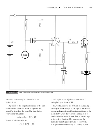
Figure 10-28 The schematic diagram for the transmitter
fluctuate from this by the influence of the The signal at the input will therefore be
microphone. multiplied by a factor of 48.
A portion of the output determined by R4 and So, we have solved the problem of increasing
R5 is fed back into the negative input of the the amplitude or voltage of the signal, but not the
amplifier to reduce the gain. The formula for problem of providing sufficient current to drive the
calculating the gain is: laser diode. To do this, we use a transistor in a
gain (R4 R5) / R5 mode called emitter-follower. That is, the voltage
at the emitter (indicated by an arrow on the
which in this case will be:
transistor circuit symbol) tracks or follows the
(47 1) / 1 48 voltage at the base (actually, 0.5V less). It will