
Page 158 - 15 Dangerously Mad Projects for the Evil Genius
P. 158
136 15 Dangerously Mad Projects for the Evil Genius
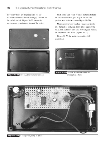
Two other holes are required: one for the Stick some thin foam or other material behind
microphone sound to enter through, and one for the microphone hole, just as you did for the
the on/off switch. Figure 10-23 shows the speaker hole in the receiver (Figure 10-24).
approximate position and sizes of the holes. Make sure the laser module lines up with the
hole beneath it and glue it into place against the
pillar. Self-adhesive tabs or a blob of glue will fix
the stripboard into place (Figure 10-25).
Figure 10-26 shows the transmitter, fully
assembled.
Figure 10-24 Foam material behind the
Figure 10-23 Drilling the transmitter box microphone hole
Figure 10-25 Fixing everything in place