
Page 156 - 15 Dangerously Mad Projects for the Evil Genius
P. 156
134 15 Dangerously Mad Projects for the Evil Genius
using the same precautions as with the receiver’s Step 6. Wire Everything Together
construction. Just like with the receiver, you may
Using Figure 10-21 as a reference, wire up the
decide to use an IC socket rather than solder the IC
project so we can test it before fitting it into a
directly.
project box.
First, cut the red lead of the battery clip in half
Step 5. Solder the Remaining
and strip and tin both ends of the cut lead. Then,
Components
solder both red leads to the switch and attach the
The rest of the components can now be soldered loose end of the lead from the switch to the
onto the board. Solder the transistor first (making positive connection on the stripboard.
sure it is the right way around), and then the
Next, solder the black negative lead from the
capacitors and the electret microphone insert.
battery clip to the negative connection on the
The microphone that the author used was stripboard.
designed to be soldered to a PCB. However, you
Shorten the leads on the laser module so they
may have to solder short leads to the contacts on
are about 2 inches (50mm) and attach them to the
the microphone.
stripboard, ensuring the polarity is correct.
The microphone must also be connected the
correct way around. The contact that is also
Step 7. Test the Transmitter
connected to the case should be the negative lead,
which should be the lower contact on the Attach the battery and aim the laser onto some
stripboard. You may need to test this with a white paper. Note that if you tap the microphone or
multimeter. If the transmitter does not vary the speak loudly into it, the brightness will alter. If this
brightness of the laser, you may need to try the does not happen, then check your circuit and make
microphone insert the other way around. sure the microphone is the right polarity.
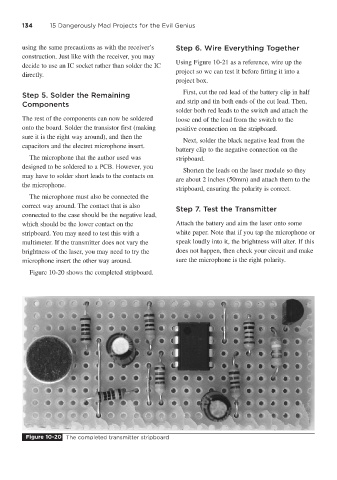
Figure 10-20 shows the completed stripboard.
Figure 10-20 The completed transmitter stripboard