
Page 154 - 15 Dangerously Mad Projects for the Evil Genius
P. 154
132 15 Dangerously Mad Projects for the Evil Genius
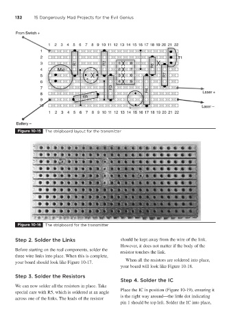
Figure 10-15 The stripboard layout for the transmitter
Figure 10-16 The stripboard for the transmitter
Step 2. Solder the Links should be kept away from the wire of the link.
However, it does not matter if the body of the
Before starting on the real components, solder the
resistor touches the link.
three wire links into place. When this is complete,
When all the resistors are soldered into place,
your board should look like Figure 10-17.
your board will look like Figure 10-18.
Step 3. Solder the Resistors
Step 4. Solder the IC
We can now solder all the resistors in place. Take
Place the IC in position (Figure 10-19), ensuring it
special care with R5, which is soldered at an angle
is the right way around—the little dot indicating
across one of the links. The leads of the resistor
pin 1 should be top left. Solder the IC into place,