
Page 153 - 15 Dangerously Mad Projects for the Evil Genius
P. 153
Chapter 10 ■ Laser Voice Transmitter 131
the microphone makes the laser shine brighter or Assembly of the Transmitter
dimmer depending on the volume of the sound.
Figure 10-15 shows the stripboard layout for the
transmitter. It is a little more complex than the
What You Will Need
receiver. It uses an operational amplifier IC and a
You will need the following components to build transistor to increase the signal from the
the laser transmitter. They are listed in the Parts microphone to a level that is large enough to drive
Bin. the laser.
You will also need the following tools to build The construction of the transmitter is described
the receiver. in the following step-by-step instructions.
T OOLBO X Step 1. The Stripboard
■ Soldering equipment
The first step is to cut a piece of stripboard that
■ A hot glue gun or self-adhesive pads has ten strips, each with 22 holes. There are then
■ A drill and assorted drill bits six breaks to be made in the tracks. Make these
using a drill bit as a hand tool, rotating it between
your finger and thumb. Figure 10-16 shows the
prepared board, ready for the components to be
soldered to it.
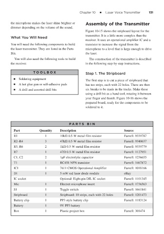
P A RT S BIN
Part Quantity Description Source
R1 1 10k 0.5-W metal film resistor Farnell: 9339787
R2–R4 3 47k 0.5-W metal film resistor Farnell: 9340637
R5, R6 2 1k 0.5-W metal film resistor Farnell: 9339779
R7 1 47 0.5-W metal film resistor Farnell: 1127951
C1, C2 2 1μF electrolytic capacitor Farnell: 1236655
T1 1 BC458 NPN transistor Farnell: 1467872
IC1 1 7611 CMOS Operational Amplifier Farnell: 1018166
D1 1 5 mW red laser diode module eBay
IC socket Optional: Eight-pin DIL IC socket Farnell: 1101345
Mic 1 Electret microphone insert Farnell: 1736563
S1 1 Toggle switch Farnell: 1661841
Stripboard 1 Stripboard: 10 strips, each with 22 holes Farnell: 1201473
Battery clip 1 PP3 style battery clip Farnell: 1183124
Battery 1 9V PP3 battery
Box 1 Plastic project box Farnell: 301474