
Page 150 - 15 Dangerously Mad Projects for the Evil Genius
P. 150
128 15 Dangerously Mad Projects for the Evil Genius
Figure 10-8 The receiver wiring diagram
loose end of the lead from the switch to the Step 6. Box the Receiver
positive connection on the stripboard.
If the receiver makes clicking noises when we
Solder the black negative lead from the battery
flash a bright light into it, we can be fairly
clip to the negative connection on the stripboard.
confident that it works okay, and go ahead and fit
That’s it. You’re done. Your receiver should now
it into a project box.
look like Figure 10-9.
It is a good idea to arrange the components in
We cannot test the receiver properly without a
the box first, working out which places are best for
transmitter, but if you connect a battery and switch
them (Figure 10-10).
the receiver on, you should hear crackling noises
From these positions, work out where to drill the
from the loudspeaker whenever you wave your hand
three holes we will make in the box lid: two large
between the phototransistor and a light source.
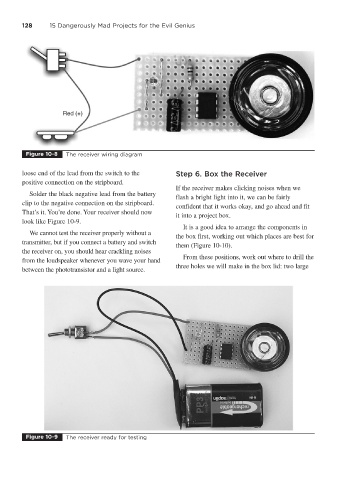
Figure 10-9 The receiver ready for testing