
Page 149 - 15 Dangerously Mad Projects for the Evil Genius
P. 149
Chapter 10 ■ Laser Voice Transmitter 127
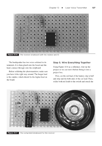
Figure 10-6 The receiver stripboard with the resistor and IC
The loudspeaker has two wires soldered to its Step 5. Wire Everything Together
terminals. It is then glued onto the board and the
Using Figure 10-8 as a reference, wire up the
leads connect through onto the stripboard.
project so we can test it before fitting it into a
Before soldering the phototransistor, make sure
project box.
you have it the right way around. The longer lead
First, cut the red lead of the battery clip in half
is the emitter, which should be the higher lead on
and strip and tin both ends of the cut lead. Then,
the board.
solder both red leads to the switch and attach the
Figure 10-7 The completed stripboard for the receiver