
Page 148 - 15 Dangerously Mad Projects for the Evil Genius
P. 148
126 15 Dangerously Mad Projects for the Evil Genius
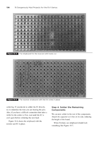
Figure 10-4 The stripboard for the receiver with tracks cut
Figure 10-5 The receiver stripboard with the link wires in place
soldering. If you decide to solder the IC directly, Step 4. Solder the Remaining
try to minimize the time you are heating the pins. Components
Also, if you have a difficult connection that takes a
We can now solder in the rest of the components.
while for the solder to flow, wait until the IC is
Attach the capacitor so it lies on its side, reducing
cool again before soldering the next lead.
the height of the board.
Figure 10-6 shows the stripboard with the
When finished, our stripboard should look
resistor and IC in place.
something like Figure 10-7.