
Page 160 - 15 Dangerously Mad Projects for the Evil Genius
P. 160
138 15 Dangerously Mad Projects for the Evil Genius
Listening to AM and FM channels, you have certain frequency (the frequency you set your dial
likely noticed that AM is of much lower quality to), and it is this wave whose amplitude or strength
than FM, and is generally used for voice rather is modulated.
than music for this reason. AM suffers from the fact that the signal is
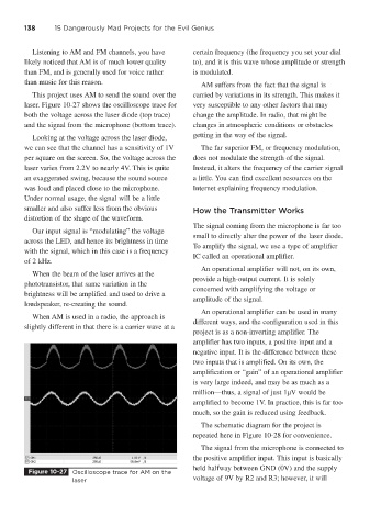
This project uses AM to send the sound over the carried by variations in its strength. This makes it
laser. Figure 10-27 shows the oscilloscope trace for very susceptible to any other factors that may
both the voltage across the laser diode (top trace) change the amplitude. In radio, that might be
and the signal from the microphone (bottom trace). changes in atmospheric conditions or obstacles
Looking at the voltage across the laser diode, getting in the way of the signal.
we can see that the channel has a sensitivity of 1V The far superior FM, or frequency modulation,
per square on the screen. So, the voltage across the does not modulate the strength of the signal.
laser varies from 2.2V to nearly 4V. This is quite Instead, it alters the frequency of the carrier signal
an exaggerated swing, because the sound source a little. You can find excellent resources on the
was loud and placed close to the microphone. Internet explaining frequency modulation.
Under normal usage, the signal will be a little
smaller and also suffer less from the obvious How the Transmitter Works
distortion of the shape of the waveform.
The signal coming from the microphone is far too
Our input signal is “modulating” the voltage
small to directly alter the power of the laser diode.
across the LED, and hence its brightness in time
To amplify the signal, we use a type of amplifier
with the signal, which in this case is a frequency
IC called an operational amplifier.
of 2 kHz.
An operational amplifier will not, on its own,
When the beam of the laser arrives at the
provide a high-output current. It is solely
phototransistor, that same variation in the
concerned with amplifying the voltage or
brightness will be amplified and used to drive a
amplitude of the signal.
loudspeaker, re-creating the sound.
An operational amplifier can be used in many
When AM is used in a radio, the approach is
different ways, and the configuration used in this
slightly different in that there is a carrier wave at a
project is as a non-inverting amplifier. The
amplifier has two inputs, a positive input and a
negative input. It is the difference between these
two inputs that is amplified. On its own, the
amplification or “gain” of an operational amplifier
is very large indeed, and may be as much as a
million—thus, a signal of just 1μV would be
amplified to become 1V. In practice, this is far too
much, so the gain is reduced using feedback.
The schematic diagram for the project is
repeated here in Figure 10-28 for convenience.
The signal from the microphone is connected to
the positive amplifier input. This input is basically
held halfway between GND (0V) and the supply
Figure 10-27 Oscilloscope trace for AM on the
laser voltage of 9V by R2 and R3; however, it will