
Page 201 - 15 Dangerously Mad Projects for the Evil Genius
P. 201
178 15 Dangerously Mad Projects for the Evil Genius
What You Will Need chapter for more information about how this circuit
works. The basic idea is that the phototransistors
You will need the following components to build control the power to the motors. The more light falling
this project. They are listing in the Parts Bin. on the left phototransistor, the more power goes to
The last seven components are only required if the right motor. This “cross-over” arrangement will
you need to make a small charger for the robot. If naturally cause the robot to home in on a light source.
you have a variable current power supply, you The following step-by-step instructions lead you
don’t need to build this part of the project. through making the robot. Everything apart from
You will also need the following tools: the motors is built onto a small piece of stripboard.
T OOLBO X
Step 1. Charge the Battery
■ Soldering equipment
We will not be able to test Snailbot if its battery is
■ A hot glue gun or self-adhesive pads
empty. So we should first charge it up.
■ A hacksaw
If you have a bench power supply with variable
■ A bright flashlight
current, then set the current to 10mA, clip the
leads to the battery’s terminals (positive to
positive), and let it charge for ten hours.
Assembly (Robot)
If you don’t have one, then you need to read the
Figure 14-2 shows the schematic diagram for the later section in this chapter called “Assembly
robot. See the “Theory” section at the end of this (Charger)” and build the battery charger first.
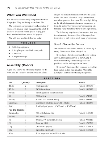
P A RT S BIN
Part Quantity Description Source
T1, T3 2 Phototransistor Farnell: 1497673
T2, T4 2 BC548 transistor Farnell: 1467872
Motors 2 Vibrating motor from toothbrush
S1 1 PCB switch Farnell: 674345
Battery 1 80mAh 2.4V MiMH battery Farnell: 854657
Stripboard 1 Stripboard; 11 strips, each with 14 holes Farnell: 1201473
1
Skid 1 Small strip of plastic 1 ⁄4" (33mm) 1" (25mm)
For the Charger
Battery clip 1 PP3-style battery clip Farnell: 1183124
Battery 1 PP3 battery
R1 1 470 0.5-W metal film resistor Farnell: 9338810
D1 1 5mm red LED Farnell: 1712786
Clip 1 Crocodile clip (red) Farnell: 1169601
Clip 1 Crocodile clip (black) Farnell: 1169604
Wire Short lengths of red and black wire