
Page 205 - 15 Dangerously Mad Projects for the Evil Genius
P. 205
182 15 Dangerously Mad Projects for the Evil Genius
Step 5. Final Wiring and Test
Using Figure 14-3 as a guide, solder the leads of
the motors to the underside of the stripboard.
We can now carry out a test to make sure
everything is right before we glue it all together.
Flip the switch to the “on” position. Both
motors should be still. If either or both of them are
turning a little, put your hand over the
phototransistors and the motors should stop. This
just means your workbench is getting too much
illumination, so find a darker place.
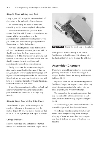
Figure 14-11 Fixing the stripboard to the plastic
Now take a flashlight and shine it in Snailbot’s
left eye. This should make the right motor whir. It
should whir faster the closer you move the flashlight and shine it directly in the face of
flashlight to it. The other motor will probably pick Snailbot and it should whir to life, chasing after
up some of the stray light and spin a little, too. You the flashlight as you move it round the table top.
should, however, be able to tell that each
phototransistor controls the opposite motor.
Assembly (Charger)
Finally, check that the motors are turning the
right way to propel Snailbot forwards. If they are If you have a variable current power supply, you
not, you may be able to turn the board through 180 probably do not need to make this charger. It
degrees without having to re-solder the connections. charges Snailbot from a 9V battery and is shown
If the leads are not long enough to do this, you will in Figure 14-12.
have to re-solder all the leads, switching the red and Figure 14-13 shows the schematic diagram for
blue leads around for each motor. Snailbot’s charger, and as you can see, it is a very
If one of the motors is not working, go back and simple design, comprised of a battery clip, an
carefully check the wiring and make sure the LED, a resistor, and two crocodile clips.
phototransistor for that motor is the right way The charger has few enough components that
around. you can just solder all the components to each
other, as shown in the wiring diagram of Figure
Step 6. Glue Everything into Place 14-14.
The stripboard is glued by its rear edge to the To use the charger, first turn the switch off. The
plastic so it is more or less centered over the crocodile clips attach directly to the battery.
motors (Figure 14-11). The excess plastic can then This charger operates at about 10mA, which
be cut off to the right length with a pair of scissors. means a full charge will require an overnight
charging of about ten hours. But once charged,
Using Snailbot you should find you get hours of fun from your
Snailbot.
Snailbot works best on a table top or other flat
surface. It does not work so well on carpet. Take a