
Page 207 - 15 Dangerously Mad Projects for the Evil Genius
P. 207
184 15 Dangerously Mad Projects for the Evil Genius
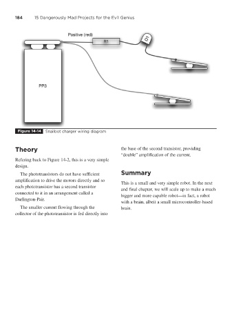
Figure 14-14 Snailbot charger wiring diagram
Theory the base of the second transistor, providing
“double” amplification of the current.
Refering back to Figure 14-2, this is a very simple
design.
The phototransistors do not have sufficient Summary
amplification to drive the motors directly and so
This is a small and very simple robot. In the next
each phototransistor has a second transistor
and final chapter, we will scale up to make a much
connected to it in an arrangement called a
bigger and more capable robot—in fact, a robot
Darlington-Pair.
with a brain, albeit a small microcontroller-based
The smaller current flowing through the brain.
collector of the phototransistor is fed directly into