Page 212 - 15 Dangerously Mad Projects for the Evil Genius
P. 212

188      15 Dangerously Mad Projects for the Evil Genius


                                                                                               8V


                                           10K   R2


                                                     T2                                          3 x AA
                                                                                                 NiMh

                                      T1

                  R1
          B          10K                            P
                                                                        M                     4V
                                   BC548
                                                     T3


                     R4

          A              1K
                                                                                                 3 x AA
                                                    N                                            NiMh
                                           R3
                                                 10K


         GND
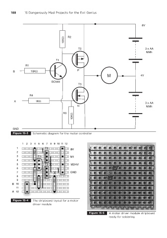
         Figure 15-3   Schematic diagram for the motor controller


         Figure 15-4   The stripboard layout for a motor
                       driver module

                                                            Figure 15-5  A motor driver module stripboard
                                                                         ready for soldering
   207   208   209   210   211   212   213   214   215   216   217