
Page 211 - 15 Dangerously Mad Projects for the Evil Genius
P. 211
Chapter 15 ■ Surveillance Robot 187
Assembling the Motor Drivers The schematic diagram for the motor controller
is shown in Figure 15-3.
These motor drivers are useful little modules that
The design uses an arrangement of two
you may well find you can use in other projects.
MOSFET transistors so the motor can be powered
They are easy to construct and do not require many
in either direction, depending on the control pins A
components.
and B. For a description of motor control designs,
see the “Theory” section at the end of this chapter.
What You Will Need
You will need the components that are listed in the Step 1. Prepare the Stripboard
Parts Bin to build each motor controller. Since we
Figure 15-4 shows the stripboard layout for one of
need two controllers, the quantities have been
the motor driver modules.
doubled. You will also need the six AA batteries,
the holder, and the clip to be able to test the The first step is to cut a piece of stripboard that
controller. has 12 strips, each with 12 holes. Two breaks must
be made in the tracks. Make these using a drill bit
You will also need the following tools:
as a hand tool, rotating it between your finger and
thumb. Figure 15-5 shows the prepared board
T OOLBO X
ready for the components to be soldered to it.
■ Soldering equipment
■ A 6V motor or Rtest (see component list)
■ A multimeter
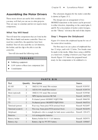
P A RT S BIN
Part Quantity Description Source
R1–R3 6 10k 0.5-W metal film resistor Farnell: 9339787
R4 2 1k 0.5-W metal film resistor Farnell: 9339779
Rtest (optional) 2 100 0.5-W metal film resistor Farnell: 9339760
T1 2 NPN bipolar transistor BC548 Farnell: 1467872
T2 2 P-channel power MOSFET FQP27P06 Farnell: 9846530
T3 2 N-channel power MOSFET FQP33N10 Farnell: 9845534
Terminal (power) 2 Four-way 5mm-pitch PCB terminal block Farnell: 9632697
Terminal (control) 2 Two-way 5mm-pitch PCB terminal block Farnell: 9632670
Stripboard 1 Stripboard—this is enough for both motor controllers Farnell: 1201473
Batteries 6 AA rechargeable batteries
Battery holder 1 Battery holder for 6 AA batteries Farnell: 3829571
Battery clip 1 Battery clip for 9V PP3 battery Farnell: 1650667