
Page 213 - 15 Dangerously Mad Projects for the Evil Genius
P. 213
Chapter 15 ■ Surveillance Robot 189
Step 2. Solder the Links and
Resistors
Before starting on the real components, solder the
four wire links into place.
We can now solder all the resistors in place.
Once done, your board will look like Figure 15-6.
Step 3. Solder the Remaining
Components
Since the terminal blocks are slightly lower in
profile than the transistors and capacitor, solder
them into place next.
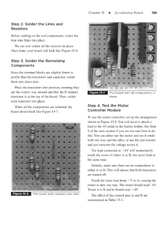
Place the transistors into position, ensuring they
are the correct way around and that the P-channel Figure 15-7 The board with all components in
transistor is at the top of the board. Then, solder place
each transistor into place.
Step 4. Test the Motor
When all the components are soldered, the
Controller Module
board should look like Figure 15-7.
To test the motor controller, set up the arrangement
shown in Figure 15-8. You will need to attach a
lead to the 4V point in the battery holder. See Step
9 of the next section if you are not sure how to do
this. You can either use the motor and see it rotate
both one way and the other, or use the test resistor
and just measure the voltage across it.
The lead connected to 8V will momentarily
touch the screw of either A or B, but never both at
the same time.
Initially, make sure there are no connections to
either A or B. This will ensure that both transistors
are turned off.
Touch the loose lead from V to A, causing the
motor to turn one way. The meter should read –4V.
Touch it to B and it should read 4V.
Figure 15-6 The board with resistors and links
The effect of the control pins A and B are
summarized in Table 15-1.