
Page 218 - 15 Dangerously Mad Projects for the Evil Genius
P. 218
194 15 Dangerously Mad Projects for the Evil Genius
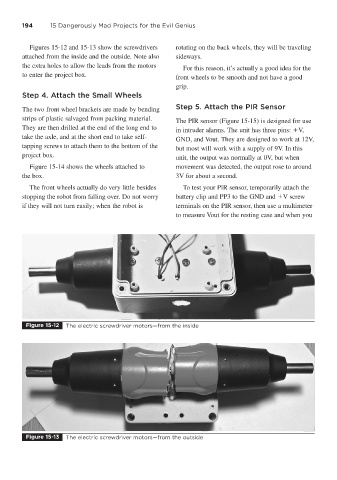
Figures 15-12 and 15-13 show the screwdrivers rotating on the back wheels, they will be traveling
attached from the inside and the outside. Note also sideways.
the extra holes to allow the leads from the motors For this reason, it’s actually a good idea for the
to enter the project box. front wheels to be smooth and not have a good
grip.
Step 4. Attach the Small Wheels
The two front wheel brackets are made by bending Step 5. Attach the PIR Sensor
strips of plastic salvaged from packing material. The PIR sensor (Figure 15-15) is designed for use
They are then drilled at the end of the long end to in intruder alarms. The unit has three pins: V,
take the axle, and at the short end to take self- GND, and Vout. They are designed to work at 12V,
tapping screws to attach them to the bottom of the but most will work with a supply of 9V. In this
project box. unit, the output was normally at 0V, but when
Figure 15-14 shows the wheels attached to movement was detected, the output rose to around
the box. 3V for about a second.
The front wheels actually do very little besides To test your PIR sensor, temporarily attach the
stopping the robot from falling over. Do not worry battery clip and PP3 to the GND and V screw
if they will not turn easily; when the robot is terminals on the PIR sensor, then use a multimeter
to measure Vout for the resting case and when you
Figure 15-12 The electric screwdriver motors—from the inside
Figure 15-13 The electric screwdriver motors—from the outside