
Page 219 - 15 Dangerously Mad Projects for the Evil Genius
P. 219
Chapter 15 ■ Surveillance Robot 195
the alarm will be triggered if the voltage goes over
500/200 or 2.5V.
Attach three wires to the PIR sensor terminals
and thread them through a hole in the lid of the
box, then glue the sensor to the box, facing
forward (Figure 15-16).
Step 6. Attach the Buzzer
The buzzer used had red and black trailing leads
for its positive and negative connections. It is
Figure 15-14 Attaching the front wheels to the attached in a similar way to the PIR sensor with a
box small blob of glue, and the leads are fed through a
hole in the lid (Figure 15-16)
wave your hand in front of it. Chances are your
sensor will behave the same; however, it may
Step 7. Attach the Proximity Sensor
produce a different output when detecting
movement. If this is the case, you will have to The IR proximity detector (Figure 15-17) is a
alter the script, in particular, the variable clever little device that uses reflected IR light to
pirThreshold. The unit of this variable is roughly determine its distance from any obstacle. It will
the voltage * 200. So a value of 500 means that measure objects ranging from 100 to 800mm.
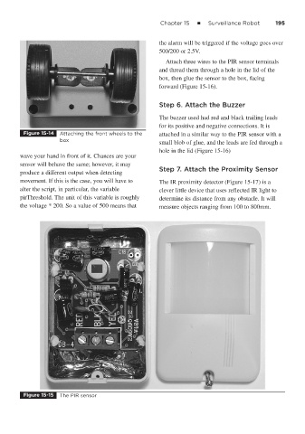
Figure 15-15 The PIR sensor