
Page 221 - 15 Dangerously Mad Projects for the Evil Genius
P. 221
Chapter 15 ■ Surveillance Robot 197
Step 9. The Switch and Batteries To find the right place, we are going to use a
multimeter. The procedure is to first measure the
Still referring to Figure 15-9, cut the red lead on
full voltage across the connectors for the battery
one of the battery clips and solder the switch to
clip. This will probably be a touch under 8V.
one side of it. The black negative lead of the
Leave the negative test lead connected to the
battery clip and the lead from the other side of the
battery negative and work your way around the
switch are connected to one side of the two-way
connectors for the cells until you find a sprung one
terminal block. Attach leads to the 2.1mm power
at about 4V. You can then tuck a wire into the
connector and fit the leads into the other side of
sprung connector.
the terminal block, each accompanied by one of
We can now wire up the leads from the motor to
the GND and V connections to the PIR sensor.
the terminal blocks on the motor controller, as well
The 2.1mm plug can then fit into the Arduino.
as the other connections from the motor controllers
Note, that we only switch the power to the 9V
to the battery and GND from the other battery.
battery. The motor controllers will effectively keep
Finally, we can plug the headers into the
the six-cell motor battery disconnected.
Arduino board. Make sure they are the correct way
The battery for the motors needs the normal V
around.
and GND supplied by a second battery clip, but
Do not plug the motor controller connector into
also requires a center supply. We will place a wire
the Arduino board until after the board is
under one of the sprung connections and then use
programmed, as you do not know the state of the
the battery to hold it in place.
output pins, and there may be the possibility of A
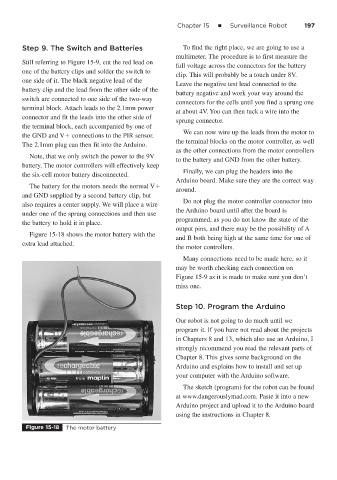
Figure 15-18 shows the motor battery with the
and B both being high at the same time for one of
extra lead attached.
the motor controllers.
Many connections need to be made here, so it
may be worth checking each connection on
Figure 15-9 as it is made to make sure you don’t
miss one.
Step 10. Program the Arduino
Our robot is not going to do much until we
program it. If you have not read about the projects
in Chapters 8 and 13, which also use an Arduino, I
strongly recommend you read the relevant parts of
Chapter 8. This gives some background on the
Arduino and explains how to install and set up
your computer with the Arduino software.
The sketch (program) for the robot can be found
at www.dangerouslymad.com. Paste it into a new
Arduino project and upload it to the Arduino board
using the instructions in Chapter 8.
Figure 15-18 The motor battery