
Page 226 - 15 Dangerously Mad Projects for the Evil Genius
P. 226
202 15 Dangerously Mad Projects for the Evil Genius
The diode is there to protect the MOSFET In this project, we sort of use half an H-bridge,
against the large back emf currents that can flow because we have a split power supply, so one side
when driving inductive loads like motors. of the motor is always connected to the middle
Life gets more complicated when we want to be voltage from the battery, and to get it to move in
able to drive the motor in both directions. To either direction, all we have to do is make the other
reverse the direction of a DC motor, just send the connection connect to either the positive supply or
current through it in the opposite direction. That ground. This is shown in Figure 15-22 in a
is, you reverse the polarity of the voltage across its simplified form using switches.
terminals, so the side that was connected to ground As with a full H-bridge, you can see that if both
becomes connected to the positive supply, and S1 and S2 are closed at the same time, there will
vice versa. be a short circuit across the battery. If S1 and S2
are transistors, then the resulting high current has
The normal approach to switching the current
nothing much to limit it and the transistors will
direction like this is to use something called an
probably be fried.
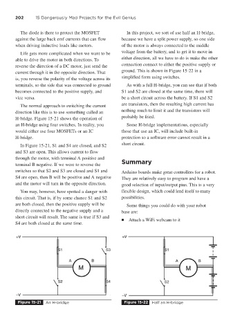
H-bridge. Figure 15-21 shows the operation of
an H-bridge using four switches. In reality, you Some H-bridge implementations, especially
would either use four MOSFETs or an IC those that use an IC, will include built-in
H-bridge. protection so a software error cannot result in a
short circuit.
In Figure 15-21, S1 and S4 are closed, and S2
and S3 are open. This allows current to flow
through the motor, with terminal A positive and
Summary
terminal B negative. If we were to reverse the
switches so that S2 and S3 are closed and S1 and Arduino boards make great controllers for a robot.
S4 are open, then B will be positive and A negative They are relatively easy to program and have a
and the motor will turn in the opposite direction. good selection of input/output pins. This is a very
You may, however, have spotted a danger with flexible design, which could lend itself to many
this circuit. That is, if by some chance S1 and S2 possibilities.
are both closed, then the positive supply will be Some things you could do with your robot
directly connected to the negative supply and a base are:
short circuit will result. The same is true if S3 and
■ Attach a WiFi webcam to it
S4 are both closed at the same time.
Figure 15-21 An H-bridge Figure 15-22 Half an H-bridge