
Page 202 - 15 Dangerously Mad Projects for the Evil Genius
P. 202
Chapter 14 ■ Light-Seeking Microbot 179
S1
Right Motor Left Motor
M M
T1 T3
T2 T4
2.4V
Left Phototransistor Right Phototransistor
BC548 BC548
Figure 14-2 The schematic diagram
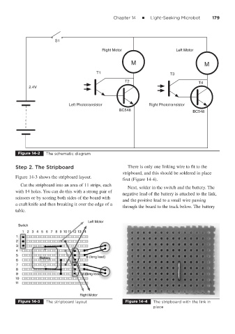
Step 2. The Stripboard There is only one linking wire to fit to the
stripboard, and this should be soldered in place
Figure 14-3 shows the stripboard layout.
first (Figure 14-4).
Cut the stripboard into an area of 11 strips, each
Next, solder in the switch and the battery. The
with 14 holes. You can do this with a strong pair of
negative lead of the battery is attached to the link,
scissors or by scoring both sides of the board with
and the positive lead to a small wire passing
a craft knife and then breaking it over the edge of a
through the board to the track below. The battery
table.
Figure 14-3 The stripboard layout Figure 14-4 The stripboard with the link in
place