
Page 36 - 15 Dangerously Mad Projects for the Evil Genius
P. 36
Chapter 2 ■ Trebuchet 17
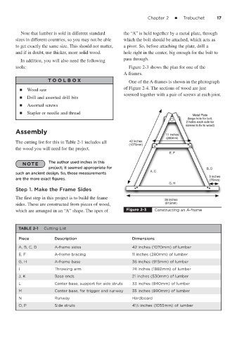
Note that lumber is sold in different standard the “A” is held together by a metal plate, through
sizes in different countries, so you may not be able which the bolt should be attached, which acts as
to get exactly the same size. This should not matter, a pivot. So, before attaching the plate, drill a
and if in doubt, use thicker, more solid wood. hole right in the center, big enough for the bolt to
In addition, you will also need the following pass through.
tools: Figure 2-3 shows the plan for one of the
A-frames.
T OOLBO X One of the A-frames is shown in the photograph
■ Wood saw of Figure 2-4. The sections of wood are just
screwed together with a pair of screws at each joint.
■ Drill and assorted drill bits
■ Assorted screws
■ Stapler or needle and thread
Assembly
The cutting list for this in Table 2-1 includes all
the wood you will need for the project.
NOTE The author used inches in this
project; it seemed appropriate for
such an ancient design. So, those measurements
are the more exact figures.
Step 1. Make the Frame Sides
The first step in this project is to build the frame
sides. These are constructed from pieces of wood,
which are arranged in an “A” shape. The apex of Figure 2-3 Constructing an A-frame
TABLE 2-1 Cutting List
Piece Description Dimensions
A, B, C, D A-frame sides 42 inches (1070mm) of lumber
E, F A-frame bracing 11 inches (280mm) of lumber
G, H A-frame base 36 inches (915mm) of lumber
I Throwing arm 74 inches (1880mm) of lumber
J, K Base ends 21 inches (530mm) of lumber
L Center base, support for side struts 33 inches (840mm) of lumber
M Center base, for trigger and runway 35 inches (890mm) of lumber
N Runway Hardboard
O, P Side struts 41⁄2 inches (1055mm) of lumber
1